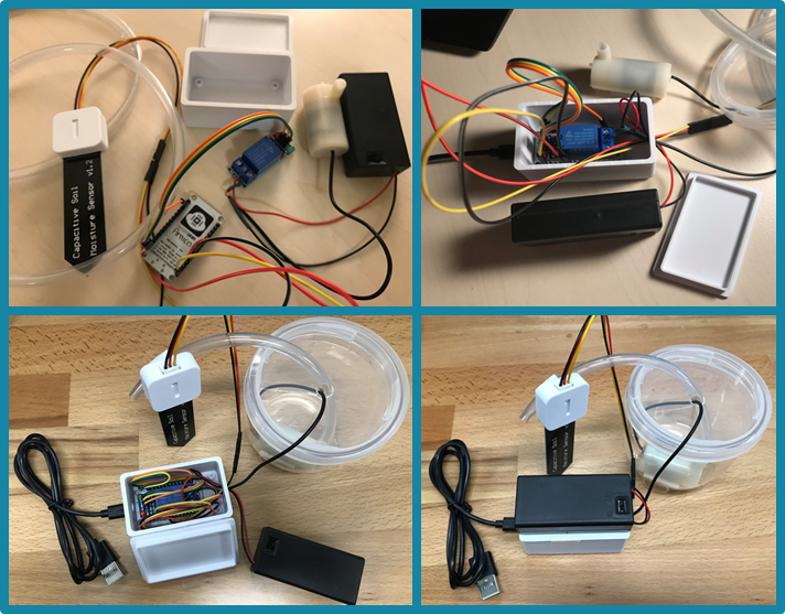
The Components/Parts
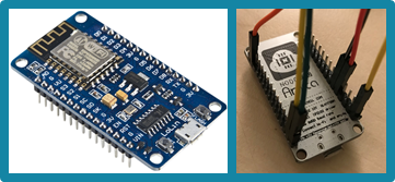
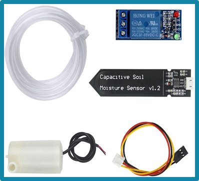
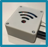
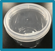
I could just stop with the robot and the Pot because both of them are already working together nicely. But from the CPS story that I just wrote recently, I have the future state for improvement, including the automatic self-watering system attached to the Pot. So I thought I want to re-challenge myself by adding this system to complete my Pot. After doing some research online and be mindful of the budget constraints, I finally found this video which I think is pretty clear to follow, including the codes that I use. And I have some of the materials available in the studio or personal property that I can use and again using the 3D printer to print the cases/holder. Here is the list of the tools and parts that I use. I only order two things from Amazon, and they are the ESP8266 and the plant watering kit (~$30). Please click on the description link below the picture for more details for the components and the 3D printer file. Below are the tools and parts that I use to make the water pump for self-watering system:

The Process
After gathering all the components and parts required to build this self-watering pump, I watched this YouTube video by Caroline Dunn who I found she’s really good at explaining the step by step on how to connect and including the code as well on the link below.
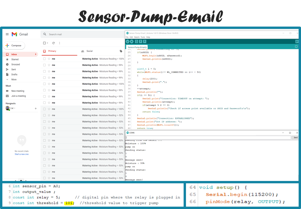
And this is the Arduino Codes used for this self-watering pump.
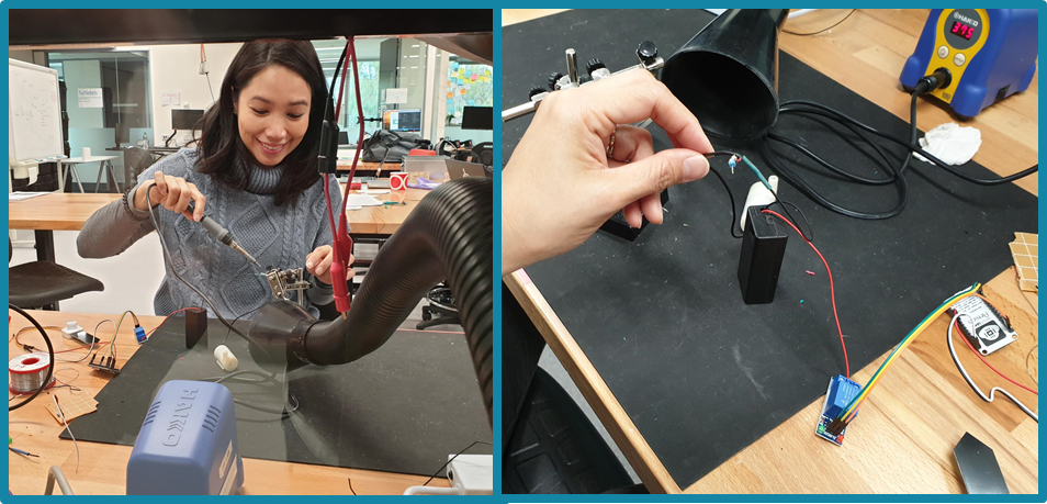
In this part, I have to learn how to solder the electrical wiring to keep everything neat and tidy. Thanks to Jake, who taught me how to use the soldering iron and always make sure don’t forget to wash your hand after each use because it has led, which is carcinogenic!
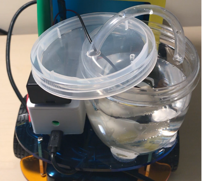
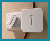
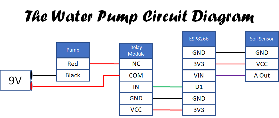
And this is the water pump circuit diagram and how the watering system all connected together neatly, ready to add at the back of the Pot and The Robot.
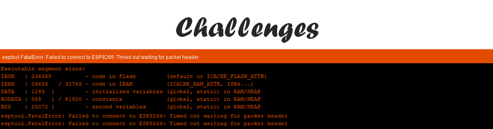
And of course, there will always be some coding challenge in this project. This time is the ESP8266. One of the error messages that I have is failed to connect and time out waiting for packet header. Again, after doing some research online to find the solution, I try to see how other people solve this issue from the online forum/discussion that is available. I tried to follow some of them, and in the end, the solution is again simple, I just change the USB port that I connect to my laptop. I also modified the code based on the test that I run to suit what I need for my project. Thanks to Mina, who helped me troubleshoot the code earlier.
- https://randomnerdtutorials.com/solved-failed-to-connect-to-esp32-timed-out-waiting-for-packet-header/
- https://forum.arduino.cc/t/esp-8266-timed-out-waiting-for-packet-header/597634
- https://www.esp8266.com/viewtopic.php?p=87515
- https://stackoverflow.com/questions/37742559/esp266-timed-out-waiting-for-packet-header
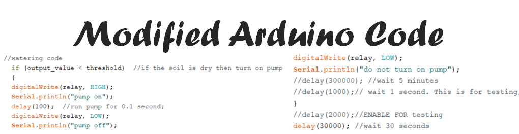
This is how the code finally works and sends an email notification to the email address that I created, especially for the Cat RoPot — and I modified the threshold code based on the test that I’ve done to trigger the pump.
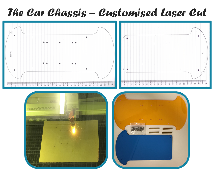
Guess what, after all that hard work, the challenge is not over yet. When I try to put everything in my robot together, the pot and the watering system, I can’t fit them all on top of the robot, so I have to modify and extend the robot now to be able to fit them all in.
To overcome this challenge, I learn how to design and use the laser cutting machine. From drawing the chassis on a piece of paper to then scan in PDF and use the Adobe Illustrator to trace and format the picture and finally send it to the Trotec laser cutting machine to print and cut. It’s another learning curve for me. Thanks to Chloe and Sarah to learn this together in the Maker Space last week before the Demo Day.
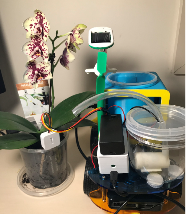
Now that the robot has been modified, I need to adjust and organise all the parts to fit in nicely.
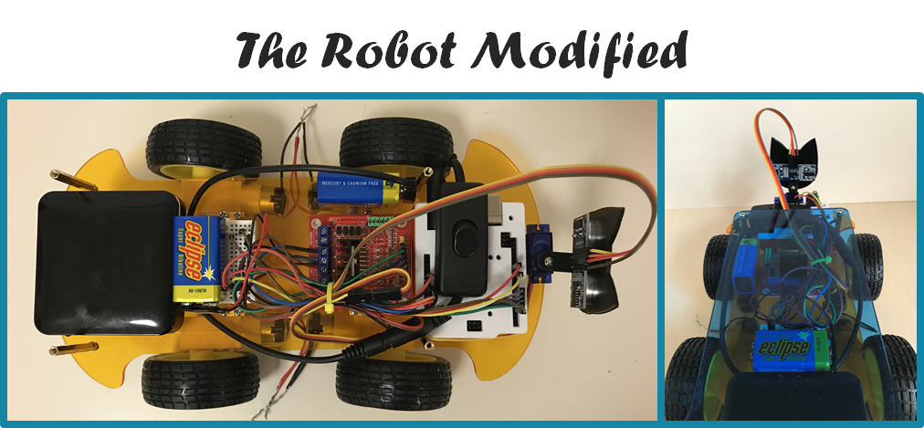
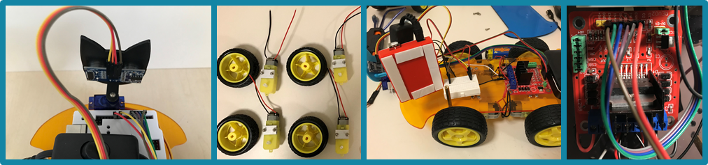
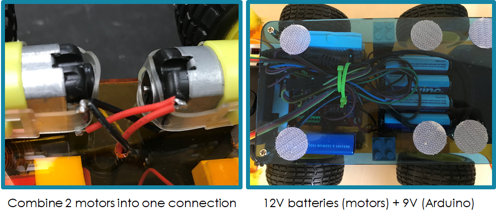
I have one tiny design error: I didn’t make the hole big enough to fit in the motor cables now that I have 4 motors instead of 2 initially. To overcome this challenge, I combined the wires and made them into 2 cables by cutting and soldering the other 2 cables to each other based on the basic circuit knowledge that I learn so far + with + and – with -. Another challenge was because the robot is now longer and heavier, I need more power to run the robot, so I use 12V batteries instead of 9V initially.
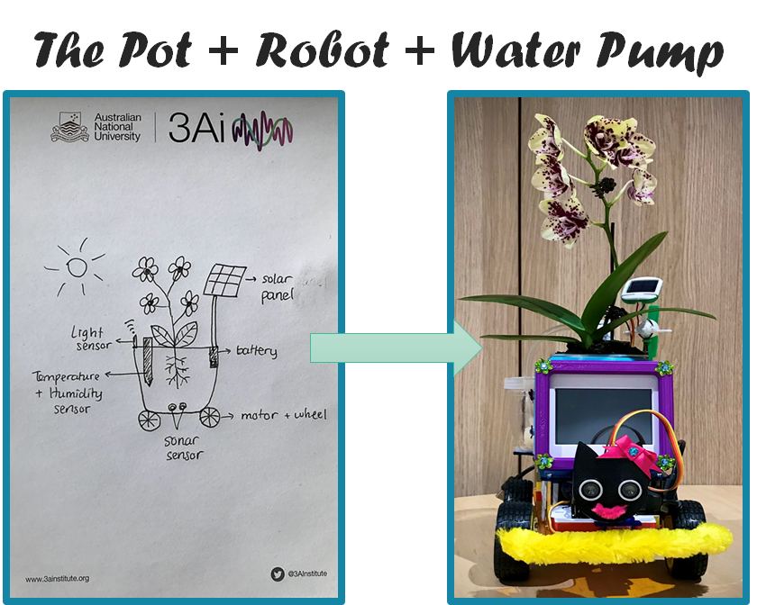
This is what my final prototype of Cat RoPot looks like from the original sketch I did initially. The only thing that is still missing is the light sensor where in the future state, I vision this Cat RoPot will move towards the sun when the orchid needs some sunlight and away when it had enough.
You can find the final codes that I used for this water pump on this link: The Water Pump Codes
Overall, making this automatic water pump was a great experience and learning progress for my circuits and coding in Python skill using new devices that I’ve never used before, ESP8266 and Relay Module. I believe through these many failures and successes in troubleshooting making this Cyber-Physical System prototype (automatic watering system) with sensors, actuators, email notification, WIFI connection, I have progressed my level from Novice to Advance Beginner/Competent. I’m looking forward to more experiments in building CPS for the rest of this year.