
Introduction
For fortnight 4 homework, we had to create a “creature”, a simple machine that consists of a Circuit Playground Express (CPE), which translates a sensor input to an actuator action and should work when only connected to a battery pack. We had to pick at least one sensor and one actuator from the list provided, and everyone had to have a unique combination. One of the sensors/actuators must be internal to the CPE, and the other must be external (connected via a circuit). This homework has expanded my new knowledge on circuitry by introducing sensors and actuators, which led to the creation of The 3A Guilty Robot Sister.
It took me a while to develop the “creature” idea as I don’t know which sensor-actuator combination I should select. One day I saw the ‘3Ai guilty robot’ big banner in the middle of the kitchen area, which inspired me to make the girly ‘sister’ version.
The previous fortnight, we use CPE, so I’m a little familiar with it this time. And at this point I know how to assemble a simple circuit, but I have to learn for the first time how to assemble a circuit with the accelerator sensor on CPE that can activate the actuator (micro servo) which I have never used it before.
The Components
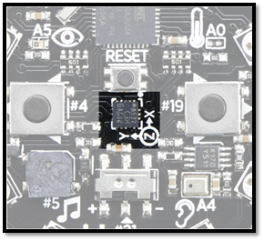
- Primary Sensor = 2 x Circuit Playground Express (CPE) – one for the head and the other one for the arm + bottom part. I choose the D27 Motion sensor -accelerometer as the built-in sensor, which is activated by tapping/shaking the CPE.
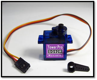
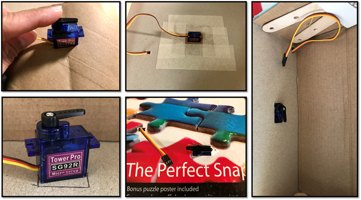
- Primary Actuator = 2 x Micro Servo SG92R, which can rotate its arm from 0-180˚ angle. I selected this actuator because like to see some actions and visualise it through the robot’s head and arms movements.
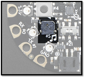
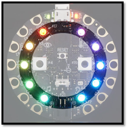
- Secondary Actuators = CPE mini speaker and Neopixels. I added the mini speaker to play some tones and music for the sound effects as the robot moves to make it more interesting. I also added the neopixels to display some colours LED as I really love how pretty it looks.
- 6 x jumper wire alligator clips to connect the Micro Servo and CPE, the ground wires to GND, the power wires to VOUT and the signal wires to A1 (robot head) and A2 (robot arm and bottom).
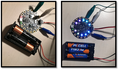
- 2 sets of 3 x AA or AAA batteries (4.5V) with the battery holder and attachment for CPE
- USB cable for CPE to connect to the computer
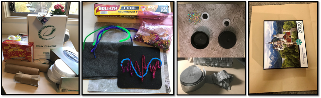
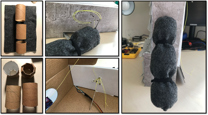
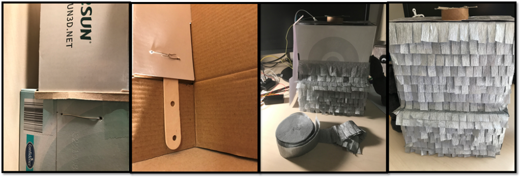
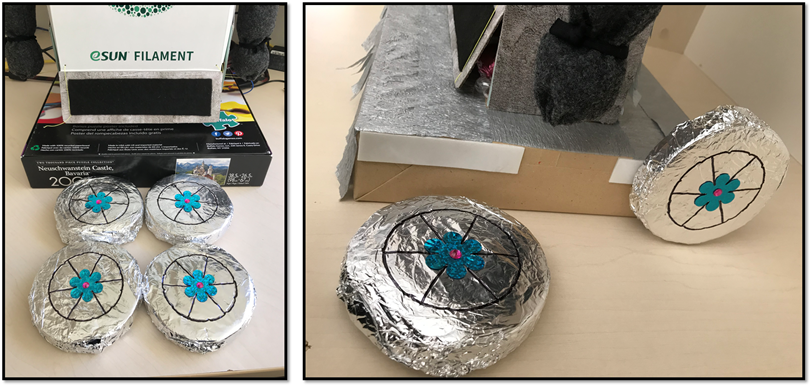
- For materials, I used any recycled boxes for the robot head (Shapes box), body (3D printer filament & tissue box) and the base (Puzzle box), the eyes (bottle lids), toilet paper and paper towel rolls for the arms and string to tied together, arts and crafts paper, brown paper, round shapes Styrofoam, colourful pipe cleaners, black and grey felt fabric, aluminium foil, shiny flowers and diamonds from the 3Ai studio and I bought the streamer paper and googly eyes from hot dollar shop.
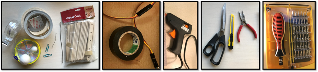
- For tools, I used the following: Sticky tape, Masking tape, Electrical tape, Double-sided tape, Electrical tape, String, thread and needles, Metal art wire for the antenna, Wooden Paddle pop sticks , Hot glue gun, Scissors, Blades/cutter, Pliers and Screw driver.
The Process
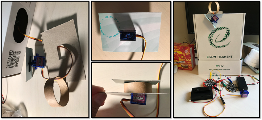
- Prepare all the components and tools, download and read the information for the sensors that we will be using, especially the right pin connection and power requirements. For me, the robot idea was inspired by this Adafruit tutorial for Drama PINATA.
- Connect the CPE to the computer using the right USB cable and create a Python code file on the CPE.
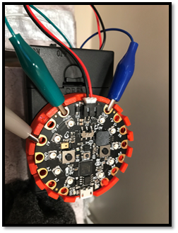
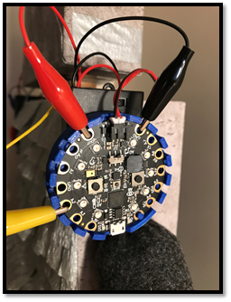
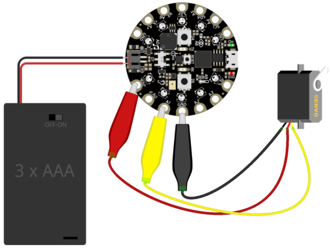
- Connect the BLACK ground wires to GND, the RED power wires to VOUT and the YELLOW signal wires to A1 (robot head) or A2 (robot arm and bottom).
- Write code from Adafruit to run the tap/shake sensor and print an output when the CPE is tap/shake to know if it is working. Some instructions use different program such as Arduino instead of CPE, or use Make Code instead of Circuit Python or Mu Editor. So I have to select and apply the right ones that I want to use and modify it to they way I would like my sensors/actuators to behave. These tutorials are reproducible only if you are using exactly the same ingredients (program, materials & tools), otherwise you can use your creativity to modify them accordingly. These are the combination of codes that inspired me and I found suitable for my robot (click the link for more details on the Adafruit tutorial):
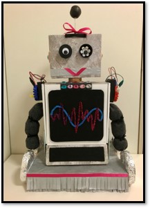
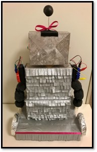
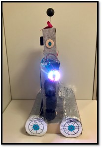
For the full codes that I used for this robot, click on any of the robot photos below:
- Connect the micro servo to the CPE as per the diagram below. Source: Using Servos With CircuitPython. Please note: for robot head, yellow cable to A1 and for robot arms and bottom, yellow cable to A2.
- Make the robot head, neck, arm, body, the base and the wheel as shown below:

- Disconnect the CPE from the computer and connect the battery pack and turn on the battery pack.
Below are the short videos for the process of making my creature robot and the robot in action.
Some challenges that I faced in completing this homework are mainly around combining the codes and how to put everything together. I did few iterations and alterations on the codes to test and find the right angle, sleep time, tone/sound and the colour brightness, speed and the robot design. I want to build a creature using technology, not only sensing and acting but also delivering a delight and surprise for people, just like what Genevieve mentioned in one of her keynote speech in 2015, The Secret Life of Big Data. For a summary text version see Bell, Genevieve (2015) The Secret Life of Big Data. In: Boellstorff, Tom and Maurer, Bill (Eds) Data, Now Bigger and Better. Chicago: Prickly Paradigm Press.
There were some weird and unexpected physical outputs occurred during the testing process. When no tap detected, the Micro Servo made a weird noise and sometimes I have to tap more than double even though I set the threshold quiet low. Later on I found out that those unexpected outputs related to the batteries that I used. When I used only the CPE (without the micro servo) 2 x AA or AAA batteries (3V) is sufficient. But when I connect the Micro Servo, it need more power so I used 3 x AA or AAA batteries (4.5V).
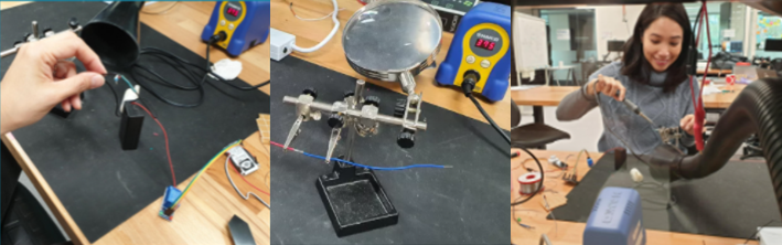
This homework also challenge my thinking on how to power a device on a battery without using the computer. On the information sheet in Adafruit, the voltage was 4.8V nominal (3V to 6V DC) with Speed : 0.1 sec/60 degree (at 4.8V). So perhaps I should be using 4 x AA or AAA batteries to make my robot powerful, but I didn’t have the battery holder compatible with CPE attachment. So I had to cut the connector from the old battery pack and connect it into the 4 batteries pack. A big thank you to Jake Blight who taught me how to use soldering machine in the Studio using some scrap wires to practice with. As a result, I was able to connect the electronic wires from my battery pack to the connector for CPE . It was a bit bumpy and not perfect, so I put over an electrical tape over the solder bit to strengthen the wires connection and to make it smoother. Learning how to use a solder proved to be a very helpful exercise for my Maker Project later on, especially for the water pump connection.
Components required for soldering:
- Soldering station machine in the Studio or Maker Space
- Alligator clamps stand holder and magnifying glass
- Exhaust fan for safety
- Rolls of lead
- Wires and other electronics to connect
- Shrink pipe
The Soldering Process:
- Turn on the exhaust fans at the soldering station.
- Power the soldering wand on at the power point and wait for it to heat up around 375 degree Celsius.
- Put the shrink pipe over each side of wires to cover the open wires so they don’t touch other electronics also for safety.
- Place the wires that we want to solder together in the clamps on the stand holder with magnifying glass.
- Once the solder wand is heated, hold it with one hand and the lead in the other hand. The hot solder wand will melt the lead, put the melt lead over the wires so it will glue/connect them together.
- Use the metal body of the wand and move along the wires to heat the shrink pipe (or use hair dryer) so the wires are covered with the pipe/cable and look cleaner.
- Once the wires connected, put the solder wand back in its holder and release the wire from the clamps.
- Remove any sharp excess bits (if there’s any) with pliers.
- Turn off the soldering power point, turn off the extractor fans and make sure you wash hands because the lead is carcinogenic (can cause cancer!).
Reflection
I think homework can be pretty challenging and take a lot of time, energy, and effort. But this homework taught me to start simple and then build the complexity of circuitry and assembly of electronics to stretch my skills further. I believe this stretch has helped me learn new skills and better understand how to use the CPE and programming them. This homework has changed my thinking of what’s possible with CPE. It is such a small device, but it has so many sensors and capabilities that it is a perfect introduction to electronics and programming. I faced some technical challenges with programming the CPE, but fortunately, Adafruit has so many tutorials and information for motion sensor and micro servo that can help me overcome those challenges.
The similarity between this homework and the previous fortnight is we use one of the CPE sensors and the same programming language in python using Mu Editor. The difference is the actuator that I select, which is a micro servo, connected using jumper wire and power by the battery to stand alone in the creature. The reflective practice has also helped me review the past experience and learn from the mistakes not to repeat the same mistakes. The changes that I think I need to make are documenting all the mistakes/challenges that I have so far in one simple form to review for improvement in the future.
This fortnight 4 homework definitely has helped me to better understand how to select the sensors and actuators, to design a CPS, a great exercise preparing for my Maker and Build projects, as well as providing me with the hands on insight into how to (de)construct a CPS in future.
Acknowledgement
Rachel from ANU Makers Space helped me with using Cura software to adjust the 3D printing for my CPE case.
Circuit Playground Express Snap Fit Mount with Alligator Clip Cutouts by paulblankenbaker
I found this design fits well, protect and make the CPE easier to be attached into my creature so I shared this case with my cohort.
Sam the PhD cohort – shared some ideas in using the IR sensor for my alternative creature if not using motion sensor.
Jake – helped me with the soldering the lose wires for my battery pack.
Matt – helped me with some ideas for my creature over Messina ice cream!
Erika – shared her idea on using 2 Micro Servos for 2 different movements.
Chloe – shared her tips on the better battery power for Micro Servo 6V (4 x AAA or 4 x AA batteries instead of 3 batteries) and where to buy it from (Jaycar).
Zac – helped me with the Python codes and fixing my CPE name issue when connected to computer.